Your plant is documented. It is not navigable.
PlantFCE Maps turns PDF P&IDs and isometrics into synchronized engineering layers for tracing equipment, lines, connected drawings, and process context.
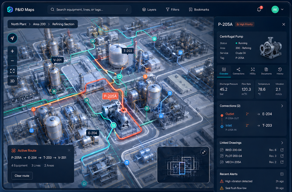
This image is for representational purposes. Product is under active development. Final UI and features may change.
P&IDs contain the plant's logic, but they were designed as static documents. Finding the right drawing, following an off-page connector, tracing a line across sheets, checking linked equipment, and reviewing changes still depends on file names, drawing numbers, manual cross-references, and experienced engineers.
Engineers often move between P&IDs and Isometrics during review, planning, and execution, but the documents do not move together. The P&ID shows process intent. The Isometric shows physical piping detail. They are not synchronized.
Maps keeps the documents engineers already trust and adds a navigable layer on top: search, click, trace, isolate, compare, switch layers, and export.
Move from equipment to lines, from lines to connected drawings, and from drawings to process context.
Select a tag or line and follow its connections across the plant.
Link P&IDs, plot plans, datasheets, isometrics, line lists, and vendor documents where needed.
Move between P&ID and isometric views like map layers. Select a line or equipment item in one layer and keep the same context when switching to another.
Follow the process logic on the P&ID, then switch to the isometric layer to see the physical piping context for review, planning, or execution.
Add temporary study overlays, compare revisions, and preserve review context.
A process plant is not understood through one drawing type. P&IDs explain how the process works. Isometrics explain how piping is built. Maps bring both into a synchronized visual workspace, so engineers can switch layers without losing the line, equipment, or document context they were reviewing.
Trace process logic, equipment, instruments, lines, and off-page connectors.
Review physical piping detail, spools, dimensions, supports, and construction context.
Select an item once and keep it active as you move between engineering views.
The workflow starts with the drawings your team already uses and ends with synchronized layers engineers can search, trace, review, and validate.
Start with the P&IDs and isometrics your team already uses.
Identify tags, equipment, lines, symbols, tables, notes, and piping references.
Link equipment, lines, off-page connectors, isometric references, and related documents.
Generate P&ID and isometric layers that stay connected by tag, line, equipment, and document context.
Search, click, trace, isolate, and switch layers without losing your place.
Validate data, add overlays, compare revisions, and export to Excel, JSON, PDF overlays, Bluebeam, or customer systems.
PlantFCE Maps is designed for the review work that already starts with P&IDs and often ends in isometrics: tracing context, checking impacts, comparing revisions, and preparing engineers to make decisions faster.
Bring P&IDs, process data, and node context into one visual workspace.
Start from the affected line on the P&ID, switch to the isometric layer, and review the physical piping context before approving a change.
Move from process systems to physical piping views to locate work areas, spools, tie-ins, and related documentation.
Follow process paths across multiple drawings without manual cross-referencing.
Use the P&ID layer for process scope and the isometric layer for piping quantities, dimensions, and construction context.
Keep process intent and physical piping detail connected during site review, punch listing, or package verification.
Designed around the engineering PDFs teams already use.
Keeps review, validation, and correction in the workflow.
Suitable for environments where engineering documents cannot be freely uploaded to third-party systems.
Developed around real process plant review, HAZOP, MOC, and project workflows.
Start with a small set of P&IDs and Isometrics. See how PlantFCE Maps links process logic and physical piping detail into a synchronized engineering map.